API 610 CENTRIFUGAL PUMP STANDARD
API 610 is the API standard relating specifically to centrifugal pumps and centrifugal pumping systems. It provides design criteria for the design of the actual centrifugal pump, as well as how the centrifugal pump is to be tested, and what type of base it is to be mounted on.
API-610 covers centrifugal pumps, and includes end suction, double suction and other types. The main focus of the API-610 is reliability, not dimensional interchangeability. This does not mean that ANSI pumps are unreliable, but rather API-610 pumps have an added aspect of robustness, due to the high temperatures and critical nature of their service.
Within the API 610 Centrifugal Pump Standard, there are various configuration codes for different types of centrifugal pumps. These are called out by a set of two letters followed by a single number. The letters are used to define the main different pump types, where OH stands for Overhung, BB stands for Between-bearings, and VS stands for Vertically Suspended. The number is used to differentiate more detailed configuration options within each section. Below are simple definitions for each API pump type. Each of the following pumps types are a sub-category of the API 610 Centrifugal Pump Standard.
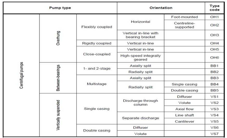
API 610 provides a classification for various types of centrifugal pumps. The API 610 pumps are primarily divided in three groups: OH, BB and VS.
OH–Overhung pumps– The impellers of these pumps protrude from the bearings. The support has to take care of all forces, e.g. the overhung mass and the rotor dynamic and hydraulic forces. The impellers of these pumps can be mounted either horizontally or vertically. Its advantages are a single bearing housing and a single seal or packing, but an overhung impeller load is a disadvantage.
BB–Between bearing pumps– The impellers of BB pumps are suspended in between the supports. For all pumps of this type, the impeller is placed horizontally, in plane with the bearings.By placing bearings on both sides of the impeller, a better support is achieved.
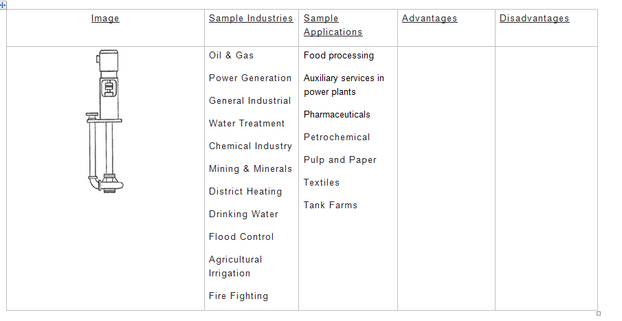
VS–Vertically suspended pumps– VS pumps are supported above the medium to be pumped. The vertically oriented impellers are suspended below the support and are submerged into the medium.
OH
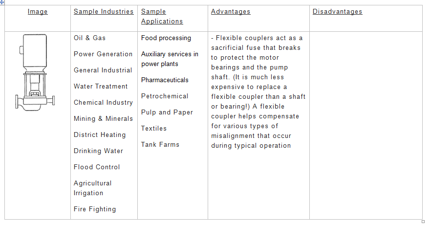
(OH) Flexibly coupled pumps feature a separate bearing assembly, in addition to the motor. Flexible couplings are usually used to transmit torque from one shaft to another when the two shafts can be slightly misaligned. They can accommodate angular misalignments up to 3° and parallel misalignment to a certain degree. In addition, they can also be used for vibration damping or noise reduction. In rotating shaft applications, a flexible coupling can protect the driving and driven shaft components (such as bearings) from the harmful effects of conditions such as misaligned shafts, vibration, shock loads, and thermal expansion of the shafts or other components.
Flex-coupled VILs are not as common as their close-coupled and rigid-coupled counterparts. This type of VIL is only offered by a handful of manufacturers. Both close-coupled and rigid-coupled VILs depend on the motor bearings to handle the thrust loads created and imposed by the spinning impeller. Not so in a flex-coupled VIL which include a thrust bearing assembly built into the pump itself. As a result, the coupling between the pump and motor can be made with a flexible coupling, and the motor does not need to be capable of handling any downthrust beyond the weight of the coupling.
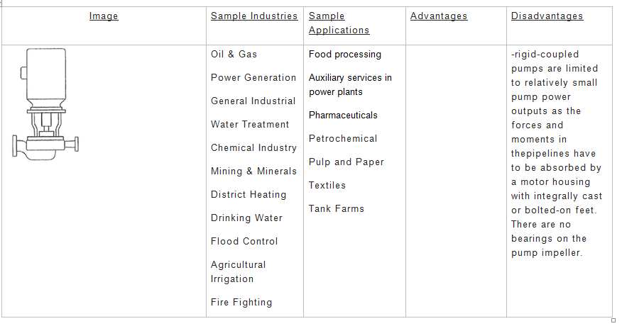
(OH) Rigidly coupled pumps also feature a separate bearing housing. Rigid couplings are designed for heavy loads or industrial equipment. They consist of short sleeves surrounded by a perpendicular flange. One coupling is placed on each shaft so the two flanges line up face to face. A series of screws or bolts then hold the flanges together. Because of their size and durability, flanged units can be used to bring shafts into alignment before they are joined together. Rigid couplings are used when precise shaft alignment is required; shaft misalignment will affect the coupling’s performance as well as its life.
Rigid-coupled VILs have a two-shaft design: a motor shaft and pump shaft coupled together with a rigid aluminum or steel coupling. The result is that the pump shaft is rigidly fixed to the motor shaft, and the motor bearings carry all of the thrust loads generated by the impeller.
Rigid-coupled VILs are often chosen for applications for which a suitable motor is not available for a close-coupled design. Close-coupled units are typically built with a standard motor with an added “c-face” – a plate mounted on the front of the motor specifically designed to make the motor suitable for close-coupling. Rigid-coupeld units, on the other hand, are typically built with a true vertical solid shaft motor.
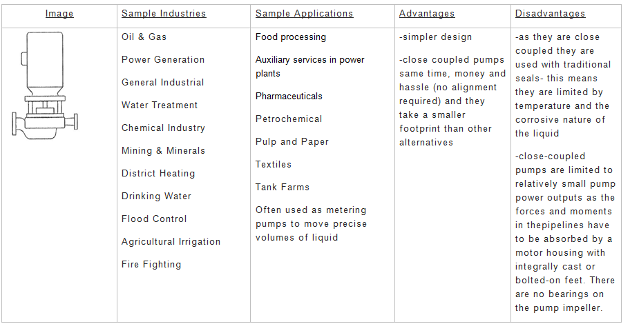
(OH) Close coupled pumps are directly mounted on an extended motor shaft. Therefore, no separate bearing assembly is needed and all forces are taken care of by the bearings in the motor. This type of construction is practical to do to dispense with the alignment problem. (OH5)
Close-coupled vertical inline pumps are commonly used for ratings up to 50 HP. The close-coupled design incorporates an impeller mounted directly on the end of the motor shaft, and a pump casing that bolts directly to the face of the motor.
Close-coupled vertical inline pumps (VIL) are the most affordable type of VIL, and several manufacturers are able to ship standard VILs in as few as two or three business days.
Vertical inline pumps – especially of the close-coupled variety are popular in the commercial building trades: HVAC, plumbing, and fire protection. They are used sparingly in other applications, primarily due to a lack of familiarity rather than any technical challenges or shortcomings.
Horizontal – At right angles to the vertical; parallel to level ground.
Vertical–Being in a position or direction perpendicular to the plane of the horizon.
(OH) In-line–A pump whose suction and discharge branches are arranged in line for direct installation into the pipework; special foundations are unnecessary, and the absence of shaft couplings eliminates alignment problems
(OH) Foot-mounted–A pump casing that is provided with feet designed for fastening the pump onto a fundamental or base plate
(OH) Centerline supported–The pump is supported on the centerline of its casing which provides for even thermal expansion on each side of the pump casing support (OH2)
(OH) Bearing bracket–These pumps have a bearing housing integral with the pump to absorb all pump loads. The driver is usually mounted on a support integral to the pump. (OH3)
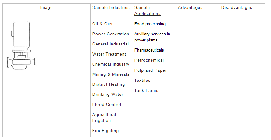
(OH) High-speed integral geared–These pumps have a speed-increasing gearbox integral with the pump. The impeller is mounted directly to the gearbox output shaft. There is no coupling between the gearbox and pump; however, the gearbox is flexibly coupled to its driver. The pumps may be oriented vertically or horizontally.
BB
(BB) 1 & 2 stage–One or two impellers and associated diffusers or volutes and return channels if required.
(BB) Multistage–A pump with three or more impellers and associated diffusers or volutes and return channels if required. (BB3) (BB4) (BB5)
Split Case Pumps– Split-case pumps (Axially Split or Radially Split) are the workhorses of industrial and municipal applications. They are more expensive than end-suction or vertical inline pumps, and not as flexible or adaptable as vertical turbines. However, what they lack in low-cost flexibility they make up for in durability, efficiency, and dependability.
The casing can be either axially or radially split, with radially split designs found in tougher applications, such as API-610, where a large gasket area of the axially split design could be a concern for leakage. In fact, axial load is nearly completely eliminated due to impeller symmetry.
A split-case pump, properly installed, designed, and operated, can provide decades of service.
(BB) Axial split–Most split-case pumps are axially-split – meaning that the flange at which the pump casing separates is in the same plane as the pump axis. Radially-split pumps are also available, and are commonly used in very high-pressure and high-temperature industrial applications (boiler-feed pumps are one common application for radially-split pumps). Split of the pump casing with the principal joint parallel to the shaft centerline. (BB1) (BB3). This impeller has two “eyes,” each receiving half of the flow. This design uses two sets of bearings, one in each bearing housing, which provide better rotor support. To reduce hydraulic radial load, a dual volute is typically used, especially on larger sizes.
So what makes split-case pumps the dependable workhorses that they are? It all comes down to design.
- Between-the-bearings: Split-case pumps are what is referred to as a “between-the-bearings” pump. This means that split-case pumps mount the impeller on a shaft that is supported by bearings on both sides of the impeller.
- Double-suction impeller: Split-case pumps are the only COMMON pump type with a double suction impeller. A double-suction impeller imposes dramatically fewer loads on the bearings than an impeller that only draws in water from one side of the impeller (single-suction).
Split-case pumps are, by-design, a more-balanced machine than most other types of pumps. Coupled with robust bearings and a maintenance-friendly casing design, split-case pumps are the design-of-choice for many municipalities and industrial facilities.
(BB) Radially split–Split of the pump casing with the principal joint perpendicular to the shaft centerline. (BB2)
(BB) Single Casing– The portion of the pump that includes the impeller chamber and volute / diffuser. This part contains a single part and is not enclosed in a pressure case or barrel.(BB4)
(BB) Double Casing– type of pump construction in which the pressure casing is separate from the pumping elements contained in the casing.The function of the second casing in a BB construction is to resist higher pressures. NOTE Examples of pumping elements include diffuser, diaphragms, bowls and volute inner casings.(BB5)
VS
(VS) Single Casing–The portion of the pump that includes the impeller chamber and volute / diffuser. This part contains a single part and is not enclosed in a pressure case or can.(VS1)(VS4)(VS5)
(VS) Double Casing–type of construction where the pump is enclosed in a second casing with a closed bottom, forming a liquid container. This effectively substitutes the wet pit, that is needed for single casing vertically suspended pumps, but still features the NPSH advantages of a submerged pump.(VS6)
(VS) Discharge through column–The discharge of the pump goes thru the same column pipe as the driven shaft for the impeller. (VS1)
(VS) Separate discharge – The discharge of the pump is a separate pipe than the column pipe where the driven shaft for the impeller goes thru. (VS4) (VS5)
(VS) Diffuser – A diffuser are stationary vanes, fitted in a diffuser casing . They convert velocity into pressure energy and guide the fluid to the impeller vanes of the subsequent stage (VS1) (VS6)
(VS) Volute – A volute is a spiral-like form such that as the liquid is discharged from the impeller into the volute casing, the volute areas increase at a rate proportional to the discharge of liquid from the impeller and a constant velocity exists around the periphery of the impeller
(VS) Axial flow– The fluid is pushed in a direction parallel to the shaft of the impeller, that is, fluid particles, in course of their flow through the pump, do not change their radial locations.
(VS) Line shaft – A line shaft is the rotating shaft part of a system of mechanical couplings between the power source the driver and the impeller. (VS4)
(VS) Cantilever– a cantilever design in which only the impeller and casing are submerged in the tank or sump. All joints, including seals, bearings, bushings, and suction check valves, are located out of the fluid. This design is ideal for moving slurries and abrasive solutions that could degrade or interfere with submerged joints. (VS5)
End Suction Pumps– A straight shot-no turns and bends-is the most efficient way to bring the flow to the impeller, and such designs are called end-suction. In the back, a mechanical seal or a set of packings separates the fluid from leaking out. Following the seal, two bearings support the entire rotor (impeller, shaft, sleeves).
For end-suction designs, the impeller is cantilevered against the inner bearing. On the positive side, there is no restriction to incoming flow, which would be caused by placing one of the bearings at the front side-also called a between-bearing design. Cantilevering the impeller against the inner bearing also helps efficiency and makes the design simple and less expensive (with only one seal).
However, a long cantilevered rotor is prone to deflections, which may overload the bearings and cause seal failures. For this reason, rotor stiffness is an important factor, and designs with bigger shafts (D) and lower overhung length (L) tend to be more reliable. The factor L3/D4, a coefficient of proportionality between force and deflection, is a good measure of comparison between similar designs. The lower the L3/D4, the more robust the rotor-which results in better resistance to deflections.
Only end-suction pumps are covered by dimensional interchangeability specification, but not all of them are covered. In the chemical industry, plants tend to have a great number of similar pumps, and interchangeability and reduction of spare parts are important considerations. ANSI B73.1, which covers such end-suction pumps, requires that all major outside dimensions are the same regardless of the manufacturer.
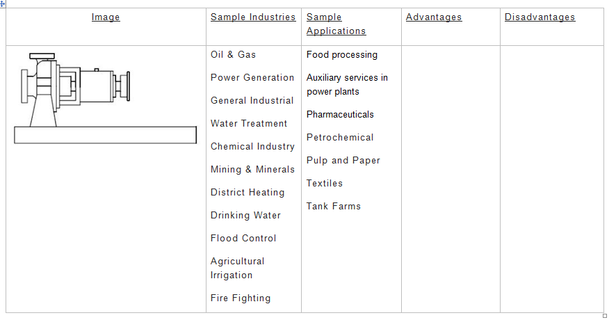
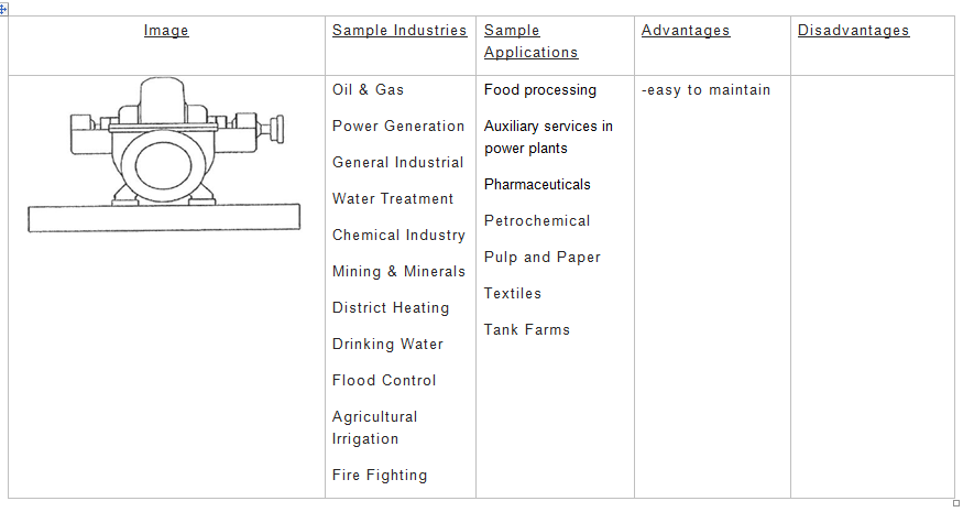
API OH1 Centrifugal Pump
The API OH1 is a horizontal, foot mounted, single stage, overhung pump with end suction. The pump is mounted to a baseplate and driven via a flexible coupler.
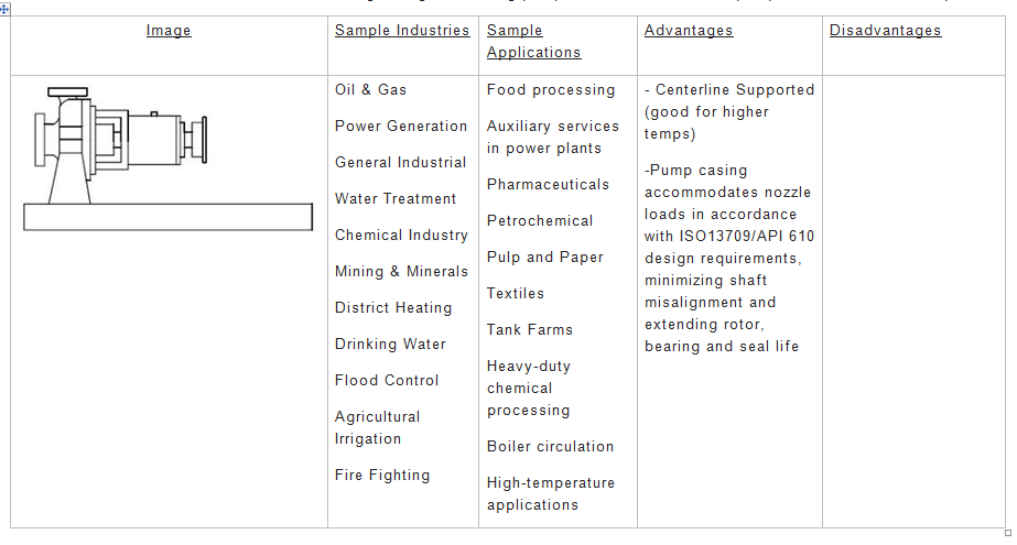
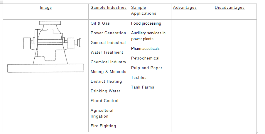
API OH2 Centrifugal Pump
The API OH2 is a horizontal, centerline mounted, single stage, overhung pump with end suction and a single bearing housing. The single bearing housing helps absorb the forces imposed on the pump shaft and maintain the position of the rotor during pump operation.
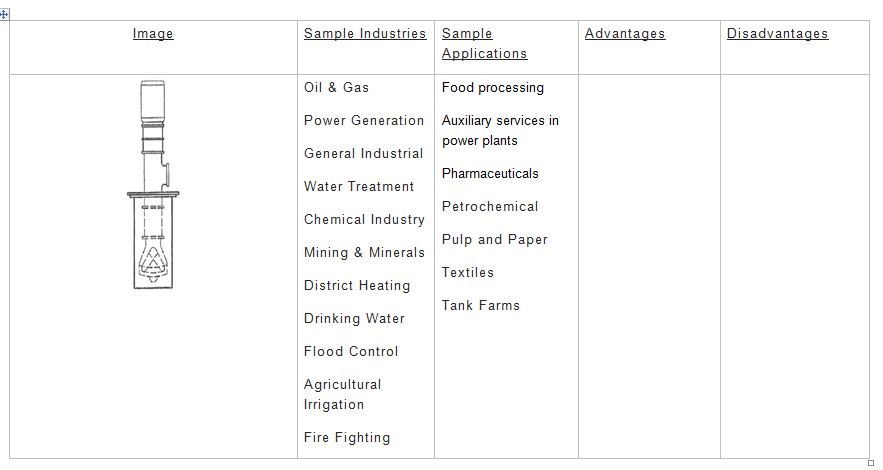
API OH3 Centrifugal Pump
The API OH3 is a vertical inline, single stage, overhung pump with separate bearing brackets. The bearing housing is integral with the pump to help absorb the loads imposed on the pump, and the motor is generally mounted on a support that is also integral with the pump. The pump and motor are coupled with a flexible shaft coupling.
————————————————————————————————————-
————————————————————————————————————-
API OH4 Centrifugal Pump
The API OH4 pump is a vertical inline, single stage, overhung pump with a rigid coupling on the pump and motor shafts. The C-face of the motor is mounted directly to the pump housing.
————————————————————————————————————–
API OH5 Centrifugal Pump
The API OH5 pump is a vertical inline, single stage, overhung pump that is close coupled with the motor. In the close coupled design, the pump impeller is mounted directly to the motor shaft (the motor shaft is designed to be extra-long), and the C-face of the motor (machined) is mounted directly to the pump housing.
API OH6 Centrifugal Pump
The API OH6 is a horizontal or vertical, single stage, overhung, high speed pump that has an integral gearbox mounted to the pump housing. The gearbox is driven by the motor with a flexible coupling, and the pump impeller is mounted directly to the high speed shaft of the gearbox.
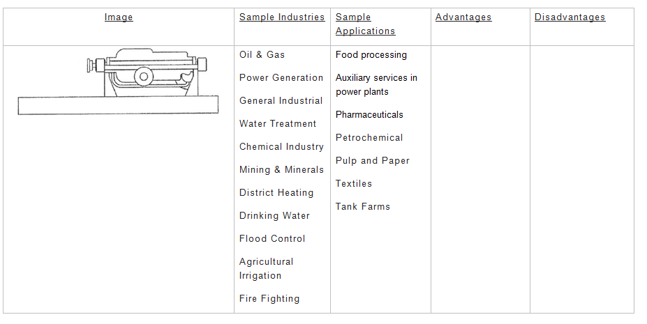
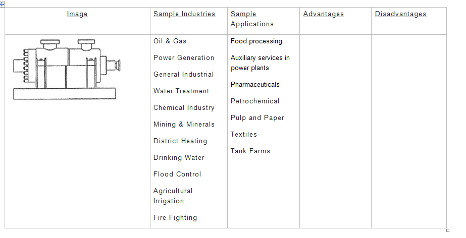
API BB1 Centrifugal Pump
The BB1 is an axially split, one or two stage pump with bearings on both ends of the rotating assembly. The pump is mounted to a baseplate and driven by a motor via a flexible coupling.
API BB2 Centrifugal Pump
The BB2 is a radially split, one or two stage pump with bearings on both ends of the rotating assembly. The pump is mounted to a baseplate and driven by a motor via a flexible coupling.
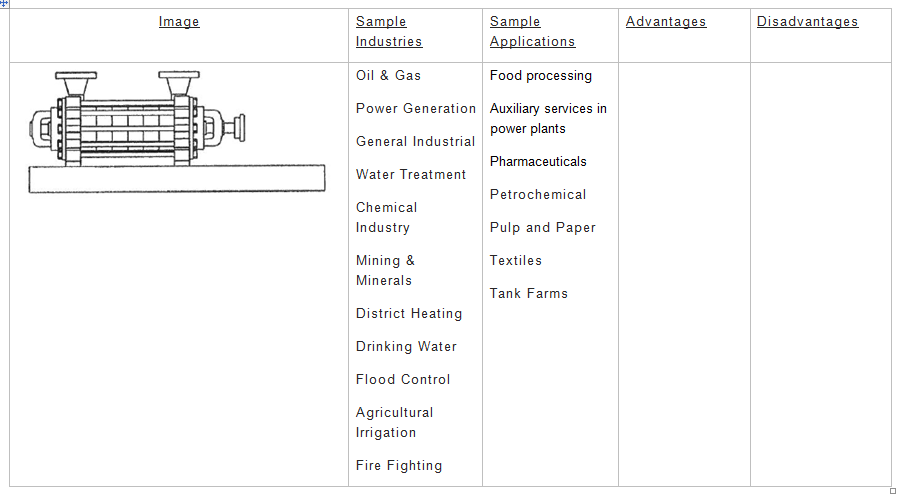
API BB3 Centrifugal Pump
The BB3 is an axially split, multistage pump with bearings on both ends of the rotating assembly. The pump is mounted to a baseplate and driven by a motor via a flexible coupling
API BB4 Centrifugal Pump
The BB4 is a radially split, multistage pump with bearings on both ends of the rotating assembly. The BB4 pump is sometimes called a tie-rod pump, segmental-ring pump, or ring-section pump, because its main housing is made up of separate, sectional pieces that are all held together by large, threaded rods.
API BB5 Centrifugal Pump
The BB5 is a radially split, multistage pump with bearings on both ends of the rotating assembly. The pump is mounted to a baseplate and driven by a motor via a flexible coupling. This pump is commonly referred to as a “barrel pumps”because the outside housing looks like a barrel. Because of its round design, the BB5 pump can be made to handle very high pressures.
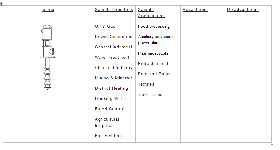
API VS1 Centrifugal Pump
The VS1 is a vertically suspended, wet pit, diffuser pump with a single casing. The discharge of the pump is routed through the upright column that suspends the bowl assemblies.
API VS2 Centrifugal Pump
The VS2 is a vertically suspended, wet pit, volute pump with a single casing. The discharge of the pump is routed through the upright column that suspends the bowl assemblies.

API VS3 Centrifugal Pump
The VS3 is a vertically suspended, wet pit, axial-flow pump with a single casing. The discharge of the pump is routed through the upright column that suspends the bowl assemblies.
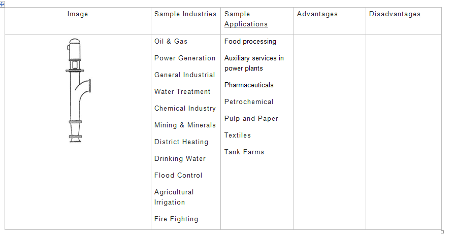
API VS4 Centrifugal Pump
The VS4 is a vertically suspended, volute pump with a single casing. This pump has the discharge column separate from the shaft column. The line shaft is supported by 1 or more bearings throughout the center column.
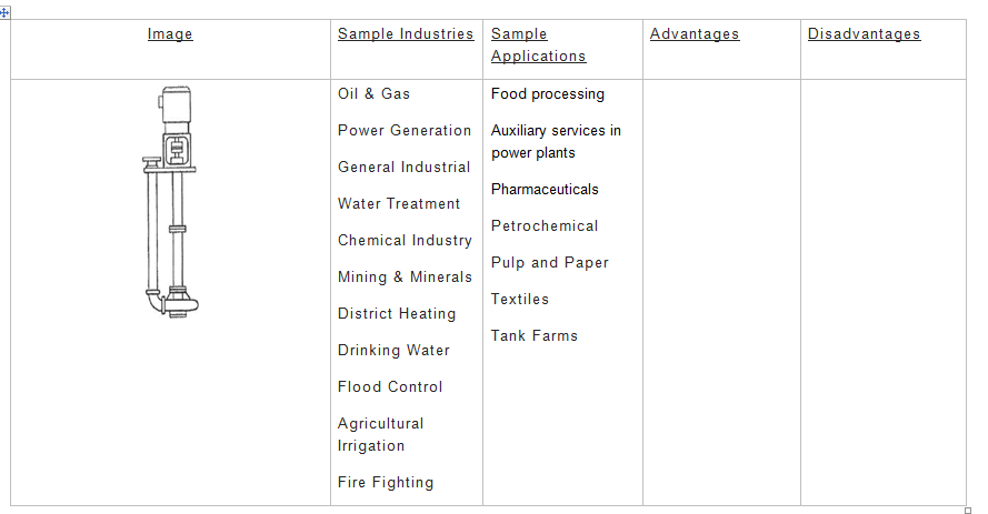
API VS5 Centrifugal Pump
The VS5 is a vertically suspended, volute pump with a single casing. This pump has the discharge column separate from the shaft column. The line shaft cantilevered and is supported only by bearings in the top housing and has no support bearing within the column.
API VS6 Centrifugal Pump
The VS6 is a vertically suspended, wet pit, diffuser pump with a double casing. The discharge of the pump is routed through the upright column that suspends the bowl assemblies. Because of the second casing around the outside of the pump, the VS6 is often referred to as a “Can Pump”.

API VS7 Centrifugal Pump
The VS7 is a vertically suspended, wet pit, volute pump with a double casing. The discharge of the pump is routed through the upright column that suspends the bowl assemblies. Because of the second casing around the outside of the pump, the VS6 is often referred to as a “Can Pump”.